Precision Conversion
Type of Source Document:
Engineering Mylars or original scribes up to 50″ width by any length.
Capability
Tooling Technologies, Inc. provides the unique service of converting hand drawn engineering documents. This includes drawings, lofted Mylars, scribes and dimensioned engineering into digital data compatible with most CAD systems. The originals are precision dimensionally-controlled drawings primarily used in the initial manufacturing of airframe detail parts. Typically the converted data is generated into a solid model and / or CNC cutter path data. TTI can convert documents up to 50 inches wide and any length.
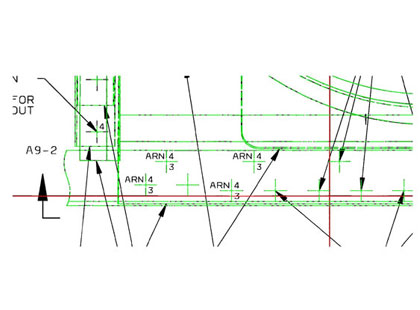
Conversion of Mylar Drawings
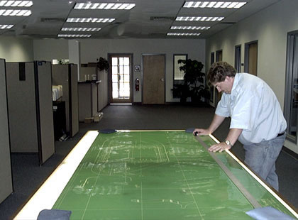
Tooling Technologies’ process is generating untold savings for aerospace manufacturers in the conversion of thousands of un-dimensioned Mylar layouts to CAD files. The traditional manual digitizing process takes approximately 100 hours per drawing and requires engineers trained in a high-end CAD system with a burden rate of about $125.00 per hour. TTI has developed our unique process, which has reduced digitizing time to 28 – 30 hours per drawing for an approximate cost of $1,500.00 – $2,000.00, a savings of $10,500.00.
As Mylars age, over time, they will yellow, shrink and warp. To compound this problem, the distortion is typically not proportional, meaning that at one end of the drawing distortion may be minimal while at the other end it is much larger, based on the condition to which the drawing was stored and exposed.
The advantages of converting Mylars to electronic CAD files are many. CAD files do not deteriorate over time, reduce the cost of engineering changes by eliminating the need to completely redraw the Mylar for any modifications, are easily duplicated and can be transferred long distances for the purpose of sharing work loads among other engineering groups, design review and providing detailed information to support personnel. CAD files also offer the ability to establish a database so they can be quickly retrieved.
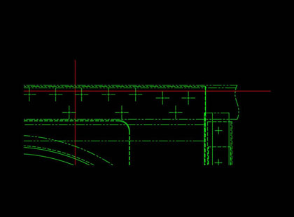
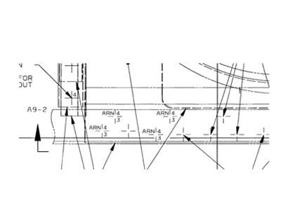
Most aircraft in operation today were created from manual layouts that need to be converted to CAD files in order to improve long-term logistical support. These drawings are un-dimensioned, contain complex geometrical entities, and are typically generated on a stable base Mylar. To maintain manufacturing integrity, the results of any such translation must be a precise representation of the original drawing.
Tooling Technologies’ precision conversion method provides a cost effective method of converting source documents into electronic files with an extremely high level of accuracy.
Software
TTI’s flagship service is reverse engineering of engineering Mylars and production parts as well as complex form dies and sophisticated tooling. The advancements in software technology and the aggressive nature of TTI’s research and development have led to the success of the precision document conversion service division.
Output Format
Our converted data is compatible with Unigraphics, Pro/Engineer, Step and a variety of other Hi-End CAD and CADCAM design stations as well as low end desk top CAD systems. IGES, DWG, DXF, TIF, BMP, ASCII and TEXT (other formats available).
Delivery Media
TTI provides electronic data in a variety of formats; Thumb Drive, CDDVD, 3.5 inch and AIT-1 or AIT-2 8mm tapes. Additionally, the data can be delivered electronically via E-mail or FTP over the Internet.
Indexing
TTI will provide an index for all converted data. At a minimum, the index will consist of the document number, document title, page number, revision level, date and purchase order and TTI job number reference.
Backup Copy
TTI will maintain a backup copy of all data generated. The backup copy will be maintained for a period of 12 months after project completion, unless otherwise specified for a different period by the order.
Equipment
Tooling Technologies incorporates the use of the cutting edge technology in equipment and software as related to precision document scanning. TTI has multiple CAD stations, precision scanners and plotters to service all your conversion needs.
Conversion of Mylars to CAD files offers the following savings:
- Integration of documents to customers’ CAD to CAM environment
- UniGraphics
- Man hours to retrieve & store documents
- Shipping Mylars or copying to other facilities
- Expensive engineering time
- Expensive storage space
- Risk of lost documents
Whether it’s a high volume automatic automotive application or the development of a uniquely specialized process, TTI is willing and able to pursue any challenge.